2019年2月16日土曜日
raspberry pi python3起動時実行
/etc/xdg/lxsession/LXDE-piに
autostartファイルに次を追加で起動成功2019.2.14
@python3 /home/pi/wk/py_wk/p.y
2019年2月9日土曜日
RaspberryPi 起動したらプログラムが動いてほしい

RaspberryPiを買って、ずっとHDMIとかでディスプレイにつなげて使ってる人は稀ですよね。最初の設定でちょっと使うけれど、ネットワークの設定とかが済んだらパソコンからssh接続したほうが楽ですからね。
そうやってRaspberryPiを使ってて不安なのは、起動はしてるだろうけど、どこまで起動したかわからない。ssh接続したいけど、もう起動したかな・・もうちょっとかな・・。っていうのを毎回考えてしまいます。
それとはまた別で、自律ロボットのためにRaspberryPiを使っている人は分かるとおもうのですが、毎回電源入れてネットワークで接続してプログラムを起動するというのは手間です。それに、ネットワークがない場所(屋外とか)で動かすときや万が一ネットワークがダメなときに、電源を入れ直したら動作するようになっていて欲しいのです。
少なくとも「GPIOピンに繋げたスイッチを押すとプログラムが動き出す」っていうプログラムが起動して欲しいわけです。(ややこしいけどわかるかな?)
最初に書いた起動してるか分からない問題も、起動したらLEDを点滅させるとかネットワークでなんかするとかいうプログラムを書けば解決ですよね。
起動したらプログラムが動く方法その1
Linuxが起動するときに実行させる
LinuxのOSが起動するときに、最初から入ってるプログラムがばーっと動いて実行されます。RaspberryPiをディスプレイに繋げて起動したときに見える大量の文字列は、初期設定とかネットワーク接続とかいろんな作業をしてくれているわけです。そのうちの1つとして実行する方法があります。
/etc/rc.localというファイルの exit 0 の前に書き込む方法です。
このファイルで実行するのは初期設定の変更関係にしましょう。
ネットワークのIPアドレスだとかの設定に使えます。
起動したらプログラムが動く方法その2
ログインしたときに実行させる
もう1つの方法はログインしたときに実行する方法です。
ログインしたときにプログラムを起動するのはMacやWindowsでもある機能ですよね。
/etc/profileにrc.localと同様に書き込むとログイン時に動作します。
あとは起動したときに自動ログインをするようにすればよいですね。
/etc/inittab の1:2345:respawn:/sbin/getty 38400 tty1をコメントアウトしてその下に1:2345:respawn:/bin/login -f ユーザー名 tty1 </dev/tty1>/dev/tty1 2>&1って書いて保存っと。
これで起動→ログイン→プログラムが起動という流れになります。
ちなみにsshでログインするともう1つ余分にプログラムが回るので注意。
ちょっとしたメモ
Pythonのプログラムを起動するとき普通は、
$ Python ./program.py見たいなコマンドにしますが、GPIOとかファイル操作をするときは実行権限がないとプログラムが途中で止まってしまいます。なので自動実行させる時はsudoで実行しましょう。
$ sudo python ./program.pyそれと、バックグラウンド処理(背後でプログラムを動かして他の処理をする) をしたい場合はアンパサンドをつけましょう。
$ sudo python ./program.py &sudoで実行することのもう一つの利点は、sudoのプロセスを止めるとプログラムが止まってくれることです。 killallってコマンドで一斉停止ができます。
$ sudo killall sudoなんかプログラムが暴走してるときとかに便利です。
動かない!!!
まず,ターミナルで,
と打ちます.nanoの部分はお好きなテキストエディタで.
@から始まる文がいくつか出てくるかと思います.自分の場合は,
となっていました.これに,プログラムの実行コマンドの先頭に@をつけて追記します.
という感じで.
自分の場合はapt-getでインストールしたopenCVだったため,(記事執筆時点では)python3ではなく,python2を使う必要がありました.
そのため自分は
となりました.
/home〜のディレクトリは自分の環境に合わせればいいです.DevelopPiから先は自分で作った適当なフォルダです.
入力が終わったら,nanoの場合,Ctrl+O(保存),Enter,Ctrl+X(終了)とすると,元のコマンド待機状態に戻るはずです.
あとは再起動すれば,pythonプログラムが開始するでしょう.
あとは再起動すれば,pythonプログラムが開始するでしょう.
2018/10/11追記:
autostartによる方法で動かないことがあったので,cronで動かす方法というのも試してみました.
autostartによる方法で動かないことがあったので,cronで動かす方法というのも試してみました.
2019年2月3日日曜日
thru UNIX file access to GPIO
GPIO Sysfs Interface for Userspace
==================================

THIS ABI IS DEPRECATED, THE ABI DOCUMENTATION HAS BEEN MOVED TO
Documentation/ABI/obsolete/sysfs-gpio AND NEW USERSPACE CONSUMERS
ARE SUPPOSED TO USE THE CHARACTER DEVICE ABI. THIS OLD SYSFS ABI WILL
NOT BE DEVELOPED (NO NEW FEATURES), IT WILL JUST BE MAINTAINED.

Refer to the examples in tools/gpio/* for an introduction to the new
character device ABI. Also see the userspace header in
include/uapi/linux/gpio.h

The deprecated sysfs ABI
------------------------
Platforms which use the "gpiolib" implementors framework may choose to
configure a sysfs user interface to GPIOs. This is different from the
debugfs interface, since it provides control over GPIO direction and
value instead of just showing a gpio state summary. Plus, it could be
present on production systems without debugging support.

Given appropriate hardware documentation for the system, userspace could
know for example that GPIO #23 controls the write protect line used to
protect boot loader segments in flash memory. System upgrade procedures
may need to temporarily remove that protection, first importing a GPIO,
then changing its output state, then updating the code before re-enabling
the write protection. In normal use, GPIO #23 would never be touched,
and the kernel would have no need to know about it.

Again depending on appropriate hardware documentation, on some systems
userspace GPIO can be used to determine system configuration data that
standard kernels won't know about. And for some tasks, simple userspace
GPIO drivers could be all that the system really needs.

DO NOT ABUSE SYSFS TO CONTROL HARDWARE THAT HAS PROPER KERNEL DRIVERS.
PLEASE READ THE DOCUMENT AT Documentation/driver-api/gpio/drivers-on-gpio.rst
TO AVOID REINVENTING KERNEL WHEELS IN USERSPACE. I MEAN IT. REALLY.

Paths in Sysfs
--------------
There are three kinds of entries in /sys/class/gpio:

   - Control interfaces used to get userspace control over GPIOs;

   - GPIOs themselves; and

   - GPIO controllers ("gpio_chip" instances).

That's in addition to standard files including the "device" symlink.

The control interfaces are write-only:

    /sys/class/gpio/

     "export" ... Userspace may ask the kernel to export control of
  a GPIO to userspace by writing its number to this file.

  Example:  "echo 19 > export" will create a "gpio19" node
  for GPIO #19, if that's not requested by kernel code.

     "unexport" ... Reverses the effect of exporting to userspace.

  Example:  "echo 19 > unexport" will remove a "gpio19"
  node exported using the "export" file.

GPIO signals have paths like /sys/class/gpio/gpio42/ (for GPIO #42)
and have the following read/write attributes:

    /sys/class/gpio/gpioN/

 "direction" ... reads as either "in" or "out". This value may
  normally be written. Writing as "out" defaults to
  initializing the value as low. To ensure glitch free
  operation, values "low" and "high" may be written to
  configure the GPIO as an output with that initial value.

  Note that this attribute *will not exist* if the kernel
  doesn't support changing the direction of a GPIO, or
  it was exported by kernel code that didn't explicitly
  allow userspace to reconfigure this GPIO's direction.

 "value" ... reads as either 0 (low) or 1 (high). If the GPIO
  is configured as an output, this value may be written;
  any nonzero value is treated as high.

  If the pin can be configured as interrupt-generating interrupt
  and if it has been configured to generate interrupts (see the
  description of "edge"), you can poll(2) on that file and
  poll(2) will return whenever the interrupt was triggered. If
  you use poll(2), set the events POLLPRI and POLLERR. If you
  use select(2), set the file descriptor in exceptfds. After
  poll(2) returns, either lseek(2) to the beginning of the sysfs
  file and read the new value or close the file and re-open it
  to read the value.

 "edge" ... reads as either "none", "rising", "falling", or
  "both". Write these strings to select the signal edge(s)
  that will make poll(2) on the "value" file return.

  This file exists only if the pin can be configured as an
  interrupt generating input pin.

 "active_low" ... reads as either 0 (false) or 1 (true). Write
  any nonzero value to invert the value attribute both
  for reading and writing. Existing and subsequent
  poll(2) support configuration via the edge attribute
  for "rising" and "falling" edges will follow this
  setting.

GPIO controllers have paths like /sys/class/gpio/gpiochip42/ (for the
controller implementing GPIOs starting at #42) and have the following
read-only attributes:

    /sys/class/gpio/gpiochipN/

     "base" ... same as N, the first GPIO managed by this chip

     "label" ... provided for diagnostics (not always unique)

        "ngpio" ... how many GPIOs this manages (N to N + ngpio - 1)

Board documentation should in most cases cover what GPIOs are used for
what purposes. However, those numbers are not always stable; GPIOs on
a daughtercard might be different depending on the base board being used,
or other cards in the stack. In such cases, you may need to use the
gpiochip nodes (possibly in conjunction with schematics) to determine
the correct GPIO number to use for a given signal.


Exporting from Kernel code
--------------------------
Kernel code can explicitly manage exports of GPIOs which have already been
requested using gpio_request():

 /* export the GPIO to userspace */
 int gpiod_export(struct gpio_desc *desc, bool direction_may_change);

 /* reverse gpio_export() */
 void gpiod_unexport(struct gpio_desc *desc);

 /* create a sysfs link to an exported GPIO node */
 int gpiod_export_link(struct device *dev, const char *name,
        struct gpio_desc *desc);

After a kernel driver requests a GPIO, it may only be made available in
the sysfs interface by gpiod_export(). The driver can control whether the
signal direction may change. This helps drivers prevent userspace code
from accidentally clobbering important system state.

This explicit exporting can help with debugging (by making some kinds
of experiments easier), or can provide an always-there interface that's
suitable for documenting as part of a board support package.

After the GPIO has been exported, gpiod_export_link() allows creating
symlinks from elsewhere in sysfs to the GPIO sysfs node. Drivers can
use this to provide the interface under their own device in sysfs with
a descriptive name.
Raspberry Pi GPIOなど
RPi Low-level peripherals
Hardware & Peripherals:
Hardware - detailed information about the Raspberry Pi boards.
Hardware History - guide to the Raspberry Pi models.
Low-level Peripherals - using the GPIO and other connectors.
Expansion Boards - GPIO plug-in boards providing additional functionality.
Screens - attaching a screen to the Raspberry Pi.
Cases - lots of nice cases to protect the Raspberry Pi.
Other Peripherals - all sorts of peripherals used with the Raspberry Pi.
Introduction
In addition to the familiar USB, Ethernet and HDMI ports, the Raspberry Pi offers the ability to connect directly to a variety of electronic devices. These include:
- Digital outputs: turn lights, motors, or other devices on or off
- Digital inputs: read an on or off state from a button, switch, or other sensor
- Communication with chips or modules using low-level protocols: SPI, I²C, or serial UART
Connections are made using GPIO ("General Purpose Input/Output") pins. Unlike USB, etc., these interfaces are not "plug and play" and require care to avoid miswiring. The Raspberry PI GPIOs use 3.3V logic levels, and can be damaged if connected directly to 5V levels (as found in many older digital systems) without level-conversion circuitry.
Note that no analogue input or output is available. However, add-on boards such as the Rpi Gertboard provide this capability.
Links
- For further specific information about the Raspberry Pi's BCM2835 GPIOs, see: RPi BCM2835 GPIOs.
- Sample code in many different languages is on the RPi GPIO Code Samples page
- To connect devices to the serial port (UART), see the RPi Serial Connection page.
- Sample circuits for interfacing the GPIOs with other electronics are shown on the RPi GPIO Interface Circuits page.
General Purpose Input/Output (GPIO)
Model A and B (Original)
P1 Header
 . | . | |

The Raspberry Pi Model A and B boards have a 26-pin 2.54 mm (100 mil)[1] expansion header, marked as P1, arranged in a 2x13 strip. They provide 8 GPIO pins plus access to I²C, SPI, UART), as well as +3.3 V, +5 V and GND supply lines. Pin one is the pin in the first column and on the bottom row. [2]
Revision 1 PCBs: Raspberry Pis with a revision 1 PCB (September 2012 or earlier) have a different pin assignment on the P1 connector:
- P1 pin 3 is GPIO 0 / SDA0 (not GPIO 2)
- P1 pin 5 is GPIO 1 / SCL0 (not GPIO 3)
- P1 pin 13 is GPIO 21 (not GPIO 27)
Revision 1 PCBs also do not have the P5 header (see below). See this discussion for more details of the changes between Rev 1 and Rev 2 PCBs.
P2 header
The P2 header is the VideoCore JTAG and used only during the production of the board. It cannot be used as the ARM JTAG [3]. This connector is unpopulated in Rev 2.0 boards.

Useful P2 pins:
- Pin 1 - 3.3V (same as P1-01, 50 mA max current draw across both of them)
- Pin 7 - GND
- Pin 8 - GND
P3 header
The P3 header, unpopulated, is the LAN9512 JTAG [4].

Useful P3 pins:
- Pin 7 - GND
P5 header
The P5 header was added with the release of the Revision 2.0 PCB design.

P5 Header pinout, top row
As seen from the back of the board:
| Pin Number | Pin Name Rev2 | Hardware Notes | Alt 0 Function | Other Alternative Functions |
| P5-01 | 5V0 | Supply through input poly fuse | ||
| P5-03 | GPIO28 | I2C0_SDA | ALT2 = PCM_CLK | |
| P5-05 | GPIO30 | ALT2 = PCM_DIN ALT3 = UART0_CTS ALT5 = UART1_CTS | ||
| P5-07 | GND |
P5 Header pinout, bottom row
As seen from the back of the board:
| Pin Number | Pin Name Rev2 | Hardware Notes | Alt 0 Function | Other Alternative Functions |
| P5-02 | 3.3 V | 50 mA max (combined with P1) | ||
| P5-04 | GPIO29 | I2C0_SCL | ALT2 = PCM_FS | |
| P5-06 | GPIO31 | ALT2 = PCM_DOUT ALT3 = UART0_RTS ALT5 = UART1_RTS | ||
| P5-08 | GND |

Note that the connector is intended to be mounted on the bottom of the PCB, so that for those who put the connector on the top side, the pin numbers are mirrored. Pin 1 and pin 2 are swapped, pin 3 and 4, etc.
An alternative way to attach this header is on top, at a slant away from the P1 header.
The new header can provide a second I²C channel (SDA + SCL) and handshake lines for the existing UART (TxD and RxD), or it can be used for an I2S (audio codec chip) interface using the PCM signals CLK, FS (Frame Sync), Din and Dout.
Note that the connector is placed JUST off-grid with respect to the P1 connector.
P6 header
The P6 header was added with the release of the Revision 2.0 PCB design.

P6 Pinout
| Pin Number | Pin Name Rev2 | Hardware Notes |
| P6-01 | RUN | Short to ground to reset the BCM2835 |
| P6-02 | GND |
A reset button can be attached to the P6 header.[5] Momentarily shorting the two pins of P6 together will cause a soft reset of the CPU (which can also 'wake' the Pi from halt/shutdown state).
Model A+, B+ and B2


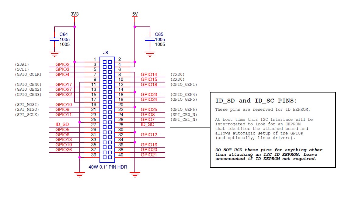
The Raspberry Pi Model A+ and B+ boards, and the Pi 2 Model B, have a 40-pin header marked J8, arranged as 2x20 pins. The first 26 pins are the same as P1 on the A/B boards, with the remaining 14 pins providing additional GPIO and ground pins, and an EEPROM ID feature for auto-configuration with add-on "HAT" boards.[6]
Interfacing with GPIO pins
GPIO voltage levels are 3.3 V and are not 5 V tolerant. There is no over-voltage protection on the board - the intention is that people interested in serious interfacing will use an external board with buffers, level conversion and analog I/O rather than soldering directly onto the main board.
All the GPIO pins can be reconfigured to provide alternate functions, SPI, PWM, I²C and so. At reset only pins GPIO 14 & 15 are assigned to the alternate function UART, these two can be switched back to GPIO to provide a total of 17 GPIO pins[7]. Each of their functions and full details of how to access are detailed in the chipset datasheet [8].
Each GPIO can interrupt, high/low/rise/fall/change.[9][10] There is currently no support for GPIO interrupts in the official kernel, however a patch exists, requiring compilation of modified source tree.[11] The 'Raspbian "wheezy"' [12] version that is currently recommended for starters already includes GPIO interrupts.
GPIO input hysteresis (Schmitt trigger) can be on or off, output slew rate can be fast or limited, and source and sink current is configurable from 2 mA up to 16 mA. Note that chipset GPIO pins 0-27 are in the same block and these properties are set per block, not per pin. See GPIO Datasheet Addendum - GPIO Pads Control. Particular attention should be applied to the note regarding SSO (Simultaneous Switching Outputs): to avoid interference, driving currents should be kept as low as possible.
The available alternative functions and their corresponding pins are detailed below. These numbers are in reference to the chipset documentation and may not match the numbers exposed in Linux. Only fully usable functions are detailed, for some alternative functions not all the necessary pins are available for the funtionality to be actually used.
There is also some information on the Tutorial on Easy GPIO Hardware & Software.
Kernel boot messages go to the UART at 115200 bit/s - there are more details on the serial port page.
P1 Header pinout, top row
| Pin Number | Pin Name Rev1 | Pin Name Rev2 | Hardware Notes | Alt 0 Function | Other Alternative Functions |
| P1-02 | 5V0 | Supply through input poly fuse | |||
| P1-04 | 5V0 | Supply through input poly fuse | |||
| P1-06 | GND | ||||
| P1-08 | GPIO 14 | Boot to Alt 0 -> | UART0_TXD | ALT5 = UART1_TXD | |
| P1-10 | GPIO 15 | Boot to Alt 0 -> | UART0_RXD | ALT5 = UART1_RXD | |
| P1-12 | GPIO 18 | PCM_CLK | ALT4 = SPI1_CE0_N ALT5 = PWM0 | ||
| P1-14 | GND | ||||
| P1-16 | GPIO23 | ALT3 = SD1_CMD ALT4 = ARM_RTCK | |||
| P1-18 | GPIO24 | ALT3 = SD1_DAT0 ALT4 = ARM_TDO | |||
| P1-20 | GND | ||||
| P1-22 | GPIO25 | ALT3 = SD1_DAT1 ALT4 = ARM_TCK | |||
| P1-24 | GPIO08 | SPI0_CE0_N | |||
| P1-26 | GPIO07 | SPI0_CE1_N | |||
P1 Header pinout, bottom row
| Pin Number | Pin Name Rev1 | Pin Name Rev2 | Hardware Notes | Alt 0 Function | Other Alternative Functions |
| P1-01 | 3.3 V | 50 mA max (01 & 17) | |||
| P1-03 | GPIO 0 | GPIO 2 | 1K8 pull up resistor | I2C0_SDA / I2C1_SDA | |
| P1-05 | GPIO 1 | GPIO 3 | 1K8 pull up resistor | I2C0_SCL / I2C1_SCL | |
| P1-07 | GPIO 4 | GPCLK0 | ALT5 = ARM_TDI | ||
| P1-09 | GND | ||||
| P1-11 | GPIO17 | ALT3 = UART0_RTS ALT4 = SPI1_CE1_N ALT5 = UART1_RTS | |||
| P1-13 | GPIO21 | GPIO27 | PCM_DOUT / reserved | ALT4 = SPI1_SCLK ALT5 = GPCLK1 / ALT3 = SD1_DAT3 ALT4 = ARM_TMS | |
| P1-15 | GPIO22 | ALT3 = SD1_CLK ALT4 = ARM_TRST | |||
| P1-17 | 3.3 V | 50 mA max (01 & 17) | |||
| P1-19 | GPIO10 | SPI0_MOSI | |||
| P1-21 | GPIO9 | SPI0_MISO | |||
| P1-23 | GPIO11 | SPI0_SCLK | |||
| P1-25 | GND | ||||
| Colour legend |
|---|
| +5 V |
| +3.3 V |
| Ground, 0V |
| UART |
| GPIO |
| SPI |
| I²C |
KiCad symbol: File:Conn-raspberry.lib[13]
Pin 3 (SDA0) and Pin 5 (SCL0) are preset to be used as an I²C interface. So there are 1.8 kohm pulls up resistors on the board for these pins.[14]
Pin 12 supports PWM.
It is also possible to reconfigure GPIO connector pins P1-7, 15, 16, 18, 22 (chipset GPIOs 4 and 22 to 25) to provide an ARM JTAG interface.[15] However ARM_TMS is not available on the GPIO connector (chipset pin 12 or 27 is needed). Chipset pin 27 is available on S5, the CSI camera interface however.
It is also possible to reconfigure GPIO connector pins P1-12 and 13 (chipset GPIO 18 and 21) to provide an I2S (a hardware modification may be required[16]) or PCM interface.[17] However, PCM_FS and PCM_DIN (chipset pins 19 and 20) are needed for I2S or PCM.
A second I²C interface (GPIO02_ALT0 is SDA1 and GPIO03_ALT0 is SCL1) and two further GPIOs (GPIO05_ALT0 is GPCLK1, and GPIO27) are available on S5, the CSI camera interface.
Referring to pins on the Expansion header
The header is referred to as "The GPIO Connector (P1)". To avoid nomenclature confusion between Broadcom signal names on the SoC and pin names on the expansion header, the following naming is highly recommended:
- The expansion header is referred to as "Expansion Header" or "GPIO Connector (P1)"
- Pins on the GPIO connector (P1) are referred to as P1-01, etc.
- Names GPIO0, GPIO1, GPIOx-ALTy, etc. refer to the signal names on the SoC as enumerated in the Broadcom datasheet, where "x" matches BCM2835 number (without leading zero) and "y" is the alternate number column 0 to 5 on page 102-103 of the Broadcom document. For example, depending on what you are describing, use either "GPIO7" to refer to a row of the table, and "GPIO7-ALT0" would refer to a specific cell of the table.
- When refering to signal names, the Broadcom name should be modified slightly to minimize confusion. The Broadcom SPI bus pin names are fine, such as "SPI0_*" and "SPI1_*", but they did not do the same on the I²C and UART pins. Instead of using "SDA0" and "SCL0", "I2C0_SDA" and "I2C0_SCL" should be used; and "UART0_TXD" and "UART0_RXD" instead of "TX" or "TXD" and "RX" or "RXD".
Power pins
The maximum permitted current draw from the 3.3 V pins is 50 mA.
Maximum permitted current draw from the 5 V pin is the USB input current (usually 1 A) minus any current draw from the rest of the board.[18]
- Model A: 1000 mA - 500 mA -> max current draw: 500 mA
- Model B: 1000 mA - 700 mA -> max current draw: 300 mA
Be very careful with the 5 V pins P1-02 and P1-04, because if you short 5 V to any other P1 pin you may permanently damage your RasPi. Before probing P1, it is a good idea to strip short pieces of insulation off a wire and push them over the 5 V pins are not accidentally shorted with a probe.
GPIO hardware hacking
The complete list of chipset GPIO pins which are available on the GPIO connector is:
(on the Revision2.0 RaspberryPis, this list changes to: 2, 3, 4, 7, 8, 9, 10, 11, 14, 15, 17, 18, 22, 23, 24, 25, 27, with 28, 29, 30, 31 additionally available on the P5 header)
As noted above, P1-03 and P1-05 (SDA0 and SCL0 / SDA1 and SCL1) have 1.8 kohm pull-up resistors to 3.3 V.
If 17 GPIOs are not sufficient for a project, there are a few other signals potentially available, with varying levels of software and hardware (soldering iron) hackery skills:
GPIO02, 03, 05 and 27 are available on S5 (the CSI interface) when a camera peripheral is not connected to that socket, and are configured by default to provide the functions SDA1, SCL1, CAM_CLK and CAM_GPIO respectively. SDA1 and SCL1 have 1K6 pull-up resistors to 3.3 V.
GPIO06 is LAN_RUN and is available on pad 12 of the footprint for IC3 on the Model A. On Model B, it is in use for the Ethernet function.
There are a few other chipset GPIO pins accessible on the PCB but are in use:
- GPIO16 drives status LED D5 (usually SD card access indicator)
- GPIO28-31 are used by the board ID and are connected to resistors R3 to R10 (only on Rev1.0 boards).
- GPIO40 and 45 are used by analogue audio and support PWM. They connect to the analogue audio circuitry via R21 and R27 respectively.
- GPIO46 is HDMI hotplug detect (goes to pin 6 of IC1).
- GPIO47 to 53 are used by the SD card interface. In particular, GPIO47 is SD card detect (this would seem to be a good candidate for re-use). GPIO47 is connected to the SD card interface card detect switch; GPIO48 to 53 are connected to the SD card interface via resistors R45 to R50.
Internal Pull-Ups & Pull-Downs
The GPIO ports include the ability to enable and disable internal pull-up or pull-down resistors (see below for code examples/support of this):
- Pull-up is 50 kOhm - 65 kOhm
- Pull-down is 50 kOhm - 60 kOhm
Driver support
The Foundation will not include a GPIO driver in the initial release, standard Linux GPIO drivers should work with minimal modification.[19]
The community implemented SPI and I²C drivers [20], which will be integrated with the new Linux pinctrl concept in a later version of the kernel. (On Oct. 14 2012, it was already included in the latest raspbian image.) A first compiled version as Linux modules is available to install on the 19/04/2012 Debian image, including 1-wire support[21]. The I²C and SPI driver uses the hardware modules of the microcontroller and interrupts for low CPU usage, the 1-wire support uses bitbanging on the GPIO ports, which results in higher CPU usage.
GordonH[22] wrote a (mostly) Arduino compatible/style WiringPi library in C for controlling the GPIO pins.
A useful tutorial on setting up I²C driver support can be found at Robot Electronics - look for the downloadable document rpi_i2c_setup.doc
SPI
There are two SPI bus brought out to the header: RPi_SPI
I²C
There are two I²C-buses on the Raspberry Pi: One on P1, and one on P5.
Note that there's a bug concerning I²C-clock-stretching, so don't use I²C-devices which use clock-stretching directly with the Raspberry Pi, or use a workaround. Details about this bug can be found at:
- http://www.raspberrypi.org/phpBB3/viewtopic.php?f=44&t=13771
- http://www.advamation.com/knowhow/raspberrypi/rpi-i2c-bug.html
MIPI CSI-2
On the production board[23], the Raspberry Pi Foundation design brings out the MIPI CSI-2 (Camera Serial Interface[24]) to a 15-way flat flex connector S5, between the Ethernet and HDMI connectors. A compatible camera[25] with 5 Megapixels and 1080p video resolution was released in May 2013.
DSI
On the production board, the Raspberry Pi Foundation design brings out the DSI (Display Serial Interface[26]) to a 15-way flat flex connector labelled S2, next to Raspberry Pi logo. It has two data lanes and a clock lane, to drive a possible future LCD screen device. Some smart phone screens use DSI[27].
CEC
HDMI-CEC (Consumer Electronics Control for HDMI) is supported by hardware but some driver work will be needed and currently isn't exposed into Linux userland. Eben notes that he has seen CEC demos on the Broadcom SoC they are using.
libCEC with Raspberry Pi support has been included in OpenELEC and will be included in Raspbmc RC4.[28]
For more information about HDMI-CEC and what you could do with it on the Raspberry Pi please see the CEC (Consumer Electronics Control) over HDMI article.
References
- ↑ raspberrypi.org
- ↑ raspberrypi.org
- ↑ http://www.raspberrypi.org/phpBB3/viewtopic.php?f=24&t=5894
- ↑ http://www.raspberrypi.org/phpBB3/viewtopic.php?f=24&t=5894
- ↑ raspi.tv
- ↑ raspberrypi.org
- ↑ raspberrypi.org
- ↑ raspberrypi.org
- ↑ http://www.raspberrypi.org/archives/384#comment-5217
- ↑ http://www.raspberrypi.org/wp-content/uploads/2012/02/BCM2835-ARM-Peripherals.pdf
- ↑ http://www.raspberrypi.org/phpBB3/viewtopic.php?f=44&t=7509
- ↑ http://www.raspberrypi.org/downloads
- ↑ http://www.raspberrypi.org/forum/projects-and-collaboration-general/gpio-header-pinout-clarification/page-2
- ↑ http://www.raspberrypi.org/forum/features-and-requests/easy-gpio-hardware-software/page-6/#p56480
- ↑ http://www.raspberrypi.org/forum?mingleforumaction=viewtopic&t=1288.1
- ↑ Forum:Sad about removal of I2S. Why was this change made?
- ↑ http://www.raspberrypi.org/forum?mingleforumaction=viewtopic&t=1288.2
- ↑ http://www.raspberrypi.org/forum?mingleforumaction=viewtopic&t=1536#postid-21841
- ↑ http://www.raspberrypi.org/forum?mingleforumaction=viewtopic&t=1278.0
- ↑ http://www.bootc.net/projects/raspberry-pi-kernel/
- ↑ http://www.raspberrypi.org/phpBB3/viewtopic.php?p=86172#p86172
- ↑ http://www.raspberrypi.org/forum/general-discussion/wiring-for-the-raspberry-pis-gpio
- ↑ http://www.raspberrypi.org/wp-content/uploads/2012/04/Raspberry-Pi-Schematics-R1.0.pdf
- ↑ http://www.mipi.org/specifications/camera-interface
- ↑ http://elinux.org/Rpi_Camera_Module
- ↑ http://www.mipi.org/specifications/display-interface
- ↑ http://en.wikipedia.org/wiki/Display_Serial_Interface
- ↑ http://blog.pulse-eight.com/2012/08/01/libcec-1-8-0-a-firmware-upgrade-and-raspberry-pi-support/
登録:
投稿 (Atom)